
€80,51 (€65,99 + IVA)

[et_pb_section bb_built="1"][et_pb_row][et_pb_column type="4_4"][et_pb_text]
| Output Shaft Style | D-shaft |
|---|---|
| Motor Type | Brushed DC |
| Output Shaft Support | Dual Ball Bearings |
| Gear Material | brass primary, nylon secondary, steel tertiary |
| Weight | 13.5 oz (382g) |
| Voltage (Nominal) | 12V |
| Voltage Range (Recommended) | 6V - 12V |
| Speed (No Load @ 12VDC) | 118 rpm |
| Current (No Load @ 12VDC) | 0.53A |
| Current (Stall @ 12VDC) | 20A |
| Torque (Stall @ 12VDC) | 958 oz-in (69 kgf-cm) |
| Gearbox Style | Planetary |
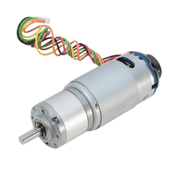
| Connector Type | PH Series JST 6-pin Connector (2mm Pitch) |
| Encoder: Cycles Per Revolution (Motor Shaft) | 12 |
| Encoder: Countable Events Per Revolution (Output Shaft) | 3,415.92 |
| Gear Ratio | 71.165:1 |
| Encoder Type | Relative, Quadrature |
| Encoder Sensor Type | Magnetic (Hall Effect) |
| Encoder Sensor Input Voltage Range | 2.4 - 26V |
| Encoder Sensor Output Pulse Amplitude | ~= Sensor Input Voltage |
The pulse amplitude of the encoder’s output square wave signal is dependent on the voltage you supply the sensor. For example, if you provide 5V to Sensor Voltage +, then Channels A & B will have a pulse amplitude of 5V.
To enhance the resolution, the encoder is attached to the motor before the gearbox.
Gear train damage can occur if stalled (locked).
[/et_pb_text][et_pb_image _builder_version="3.19" src="https://www.steplab.net/wp-content/uploads/2018/06/638263_to_638270.png?x71106" /][/et_pb_column][/et_pb_row][/et_pb_section]